Engineering Drawing Format and Contents
What does an engineering drawing contain?
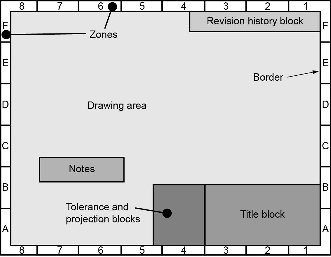
Engineering drawings have the following main areas. The placement of the components and sheet sizes are controlled by the ASME Y14.1 and ASME Y14.1M standards.
- Border & Zones
- Various blocks
- Notes
- Drawing
Sheet sizes
The following tables are the various sheet sizes used for engineering drawings.
Format size designation |
Vertical (in) |
Horizontal (in) |
Recommended number of zones |
A (Horizontal) |
8.50 |
11.00 |
2 x 2 |
A (Vertical) |
11.00 |
8.50 |
2 x 2 |
B |
11.00 |
17.00 |
2 x 4 |
C |
17.00 |
22.00 |
4 x 4 |
D |
22.00 |
34.00 |
4 x 8 |
E |
34.00 |
44.00 |
8 x 8 |
F |
28.00 |
40.00 |
6 x 8 |
G |
11.00 |
22.50 - 90.00 |
4 x (6 - 24) |
H |
28.00 |
44.00 - 143.00 |
8 x (8 - 26) |
J |
34.00 |
55.00 - 176.00 |
8 x (10.32) |
K |
40.00 |
55.00 - 176.00 |
8 x (10.32) |
Designation |
Vertical (mm) |
Horizontal (mm) |
Recommended number of zones |
A0 |
841 |
1189 |
16 x 24 |
A1 |
594 |
841 |
12 x 16 |
A2 |
420 |
594 |
8 x 12 |
A3 |
297 |
420 |
6 x 8 |
A4 |
297 |
210 |
6 x 4 |
A1.0 |
594 |
1189 |
12 x 24 |
A2.1 |
420 |
841 |
8 x 16 |
A2.0 |
420 |
1189 |
8 x 24 |
A3.2 |
297 |
594 |
6 x 12 |
A3.1 |
297 |
841 |
6 x 16 |
A3.0 |
297 |
1189 |
6 x 24 |
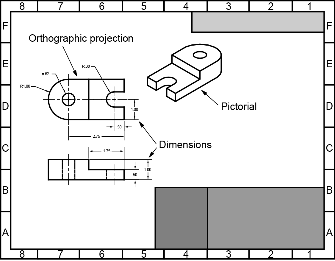
The drawing
The drawing is the most important part of the engineering drawing. The drawing describes the shape and size of the part.
Drawing scale
The scale is the ratio at which the drawing is printed to the actual size of the part. This is noted in the title block. Examples of different scales is shown below.
Half scale = 1/2 or 1:2
One quarter scale = 1/4 or 1:4
Double scale = 2:1
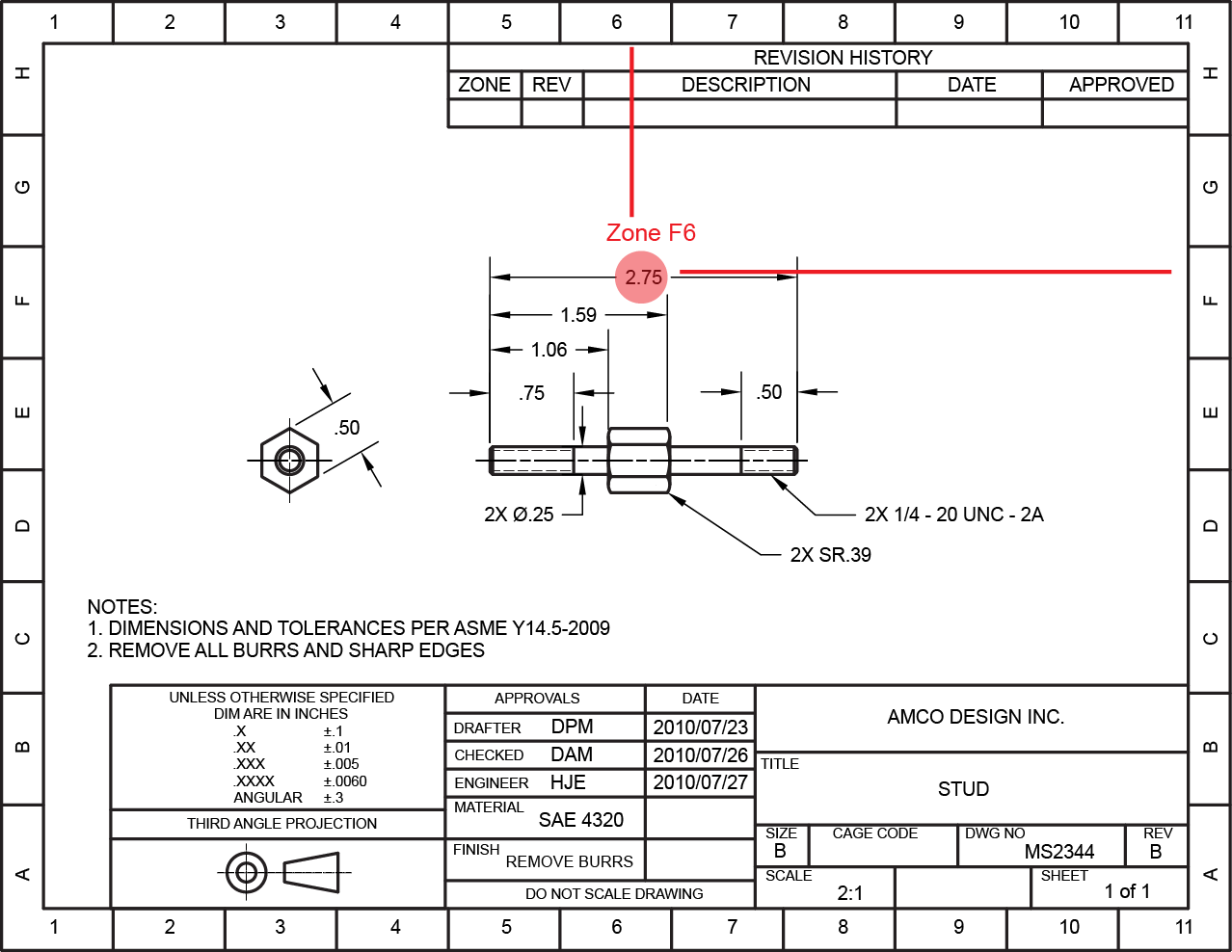
Zones
Zone provide a grid for identifying different locations on the drawing.
Drawing notes
Drawing notes provide information that clarify a particular requirement or specifies new information necessary to manufacture the object correctly. This information is preceded by the word NOTE:
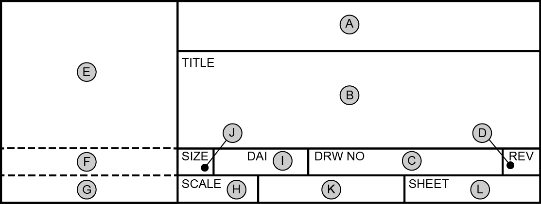
Title block
The title block gives information about the part or assembly represented in the drawing. Each area of the title block contains specific information which is controlled by the ASME Y14.100 standard.
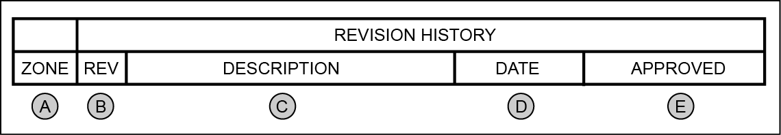
Revision History block
The revision history block gives information about any changes made to the drawing and the zone in which it occurred.
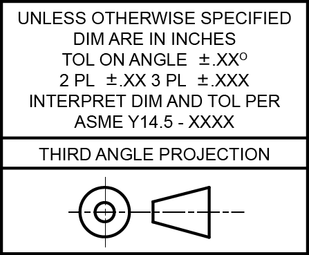
Tolerance and Projection block
The tolerance block give the default dimension tolerances and the drawing standard used to create the drawing. The projection block states which projection method was used to create the drawing.