Drawing Screw Threads
There are three methods of representing screw threads on a drawing.
- Detailed
- Schematic
- Simplified
Screw thread representation present in this chapter is in accordance with the ASME Y14.6-2001 standard.
Detailed Representation
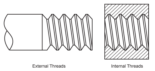
A detailed representation is a close approximation of the appearance of an actual screw thread.
What do you think the pros and cons are for this type of representation? (Add interactivity)
Schematic Representation
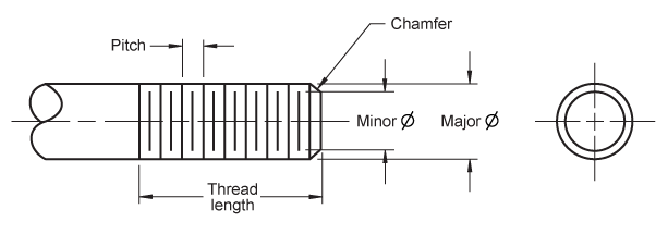
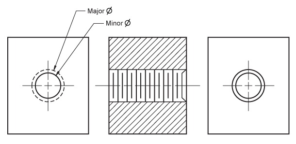
The schematic representation uses staggered lines to represent the thread roots and crests.
What do you think the pros and cons are for this type of representation? (Add interactivity)
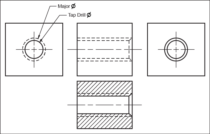
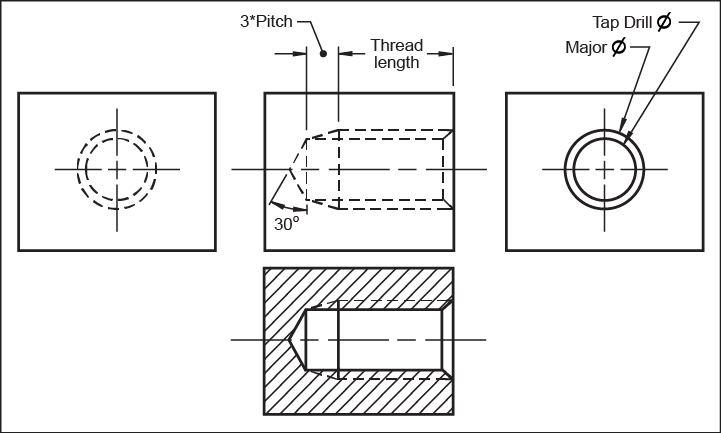
Simplified Representation
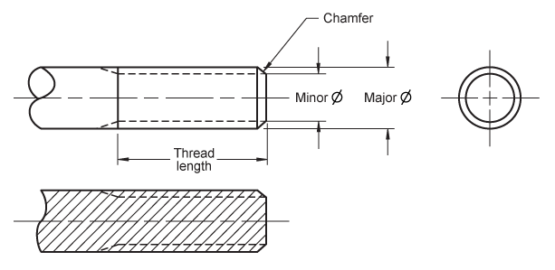
The simplified representation uses visible and hidden lines to represent the major and minor diameters.
What do you think the pros and cons are for this type of representation? (Add interactivity)
Drawing Screw Threads
Thread tables in the appendix of the Engineering Graphics Essentials book can be used to look up value for the;
- Pitch
- Minor diameter
- Tap drill diameter
If screw thread tables are not available, the minor diameter can be approximated as 75% of the major diameter.
